Power distribution and measurement Ongoing · board fabricated and in the vehicle
Eco Illini
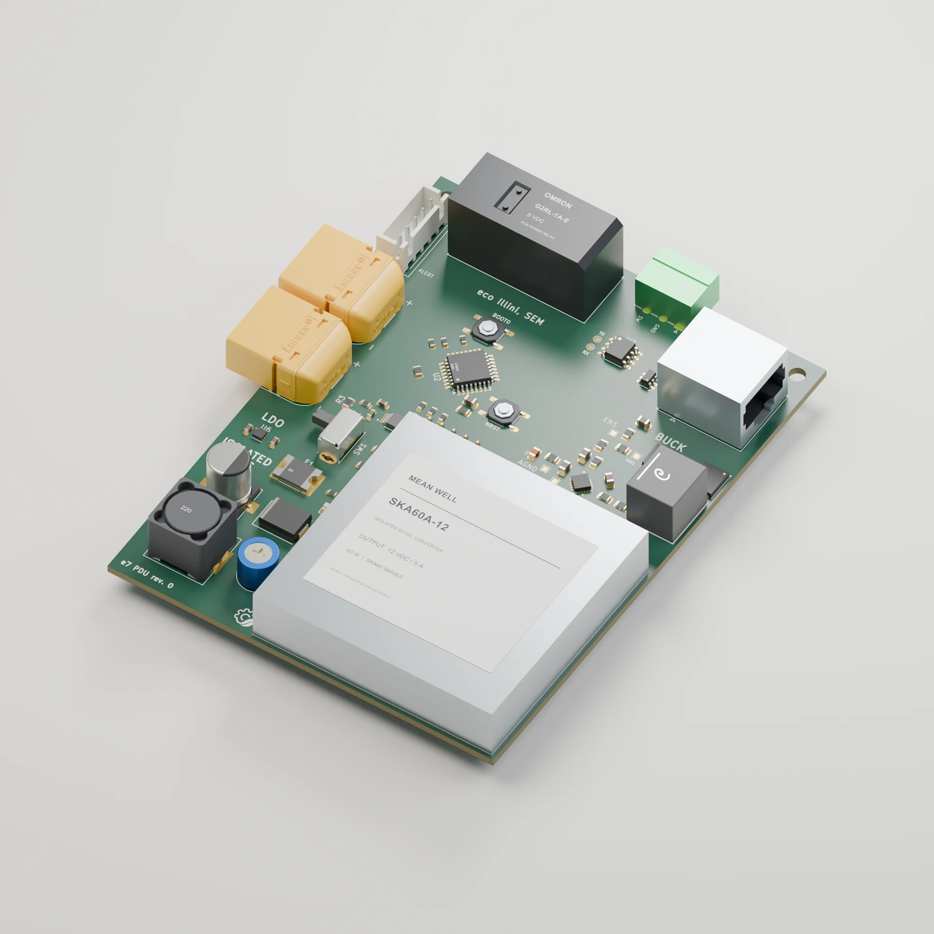
One 36 V battery powers every subsystem on the car. The power distribution board turns it into protected 12 V and 3.3 V supplies.
What I did
I designed the schematic, chose the parts and laid out the four-layer board in KiCad. I assembled the fabricated board and validated it on the bench and in the car.
I also lead the PDU and Joule Meter teams. On the Joule Meter I wrote the STM32 measurement firmware; its board layout was a team effort.
Result
- Both rails held under 50 mV peak-to-peak ripple, in LTspice and on the bench.
- Joule Meter energy readings within 1% of a calibrated supply, using an INA228 on a 10 mΩ shunt.
- 30% fewer prototype iteration cycles year over year across both teams.
- These are summary figures; scope captures and calibration logs aren't shown yet.
Design decision
Protection on the board itself
Fusing, reverse-polarity protection and the E-STOP path live on the PDU. A reversed connector or a downstream short during student assembly stays a contained failure instead of reaching the whole car.
- 12 V rail
- 3.3 V rail
- Subsystems
- Shunt10 mΩ
More detail
Constraints
Several teams build boards on different schedules, and the PDU is where they all meet. It is fabricated outside and hand-assembled by students, so parts and layout had to suit rework.
Power and protection
Power enters through fusing, reverse-polarity protection and the E-STOP path. Buck converters and LDO regulators produce the 12 V and 3.3 V rails, and the board carries temperature sensing.
Measurement is a separate branch: the INA228 reads the shunt, the STM32 turns its registers into energy, and the result goes out over CAN, SPI and I2C.
Bring-up and testing
Validation covered load regulation, transient response, thermal behaviour and in-vehicle integration. Ripple was checked in LTspice first, then with an oscilloscope.
Regulator part numbers, board dimensions and rail currents are left off this page.
Other design decisions
Buck conversion first, LDO where it helps
Switching regulators for the big step down from 36 V. Instead of: linear regulation throughout.
A linear drop from 36 V turns most of the power into heat; bucks fix that but add ripple and layout sensitivity.
Four layers
A four-layer stack. Instead of: a cheaper two-layer board.
Costs more, but solid reference planes keep return paths and regulator loops tight.